
The groma discovered in Pompeii in 1912 remained buried under volcanic ash for 1,833 years, preserving the only complete example of Rome’s signature surveying instrument. This iron cross mounted on a vertical pole with four hanging plumb bobs allowed Roman engineers to project perfectly straight lines and right angles across hundreds of miles of terrain. Marcus Vitruvius Pollio described the companion instrument called the chorobates in his architectural treatise around 15 BCE, detailing a six-meter wooden beam that measured horizontal planes with precision sufficient for constructing aqueducts across mountainous landscapes.
Roman surveyors, called agrimensores or gromatici, transformed Mediterranean geography through systematic land division beginning in the second century BCE. Military colonies established for veterans and landless citizens required rectangular land plots surveyed with geometric precision. Road networks connecting distant provinces demanded straight routes plotted across forests, rivers, and mountains. This post explains how Roman surveying instruments functioned, examining their construction, operational techniques, limitations, and the massive infrastructure projects they enabled across the empire.
Origins of the Groma
The word groma entered Latin from the Greek term gnoma through Etruscan intermediaries. Greek sources used gnomon to designate the central point of a military camp or town, though the exact meaning remains debated among linguists. The Etruscans apparently called the instrument cranema before Romans standardized the Latin term.
Greeks, Egyptians, and Mesopotamians all practiced land division into rectangular plots before Roman contact. The unprecedented scale of Roman centuriation from the second century BCE onward suggests that Romans developed their surveying methods independently rather than copying Greek practices. Peculiarities in Roman surveying terminology and techniques support this independence theory.
The groma may have originated in Mesopotamia or Greece before the fourth century BCE. Romans apparently made no improvements to the basic design after adopting it, suggesting the instrument had already achieved optimal form. All Roman writers on surveying assumed readers already understood groma construction and operation, indicating widespread familiarity with the tool.
Groma Construction and Components
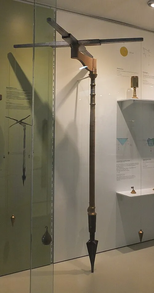
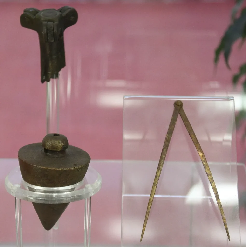
The instrument consisted of three essential parts: the stelletta, rostrum, and ferramento. The stelletta formed the distinctive horizontal cross made from hollow metal tubes reinforced with wooden cores. Two arms crossed at right angles, creating four endpoints called curnicula from which plumb lines descended.
Each plumb line terminated in a cone or pear-shaped bronze weight that stabilized the hanging thread against slight breezes. The four weights created two intersecting sight lines that the surveyor used to establish perpendicular alignments on the ground. The rostrum measured exactly one Roman foot, approximately 29.6 centimeters, providing a standard offset distance for positioning the instrument.
The ferramento constituted a hollow metal pole with a conical iron point at the base for anchoring into soil. A cylindrical socket at the top received the pivoting bracket that supported the stelletta. This bracket allowed the cross to rotate freely while maintaining its horizontal orientation.
Debate Over the Pivoting Bracket
Adolf Schulten reconstructed the first modern groma replica in 1912, proposing a pivoting bracket that offset the cross from the vertical staff. Matteo Della Corte’s discovery of the Pompeii groma soon afterward seemed to confirm this design. The offset arrangement allowed surveyors to sight along the plumb lines without the vertical pole obstructing their view.
Thorkild Schiöler challenged this interpretation in 1994, arguing that the five-kilogram iron cross from Pompeii was too heavy for a pivoting bracket to support. No archaeological evidence of such brackets has emerged from any Roman site. Tombstone carvings showing gromatici with their instruments consistently omit any visible bracket mechanism.
Archaeologists rejecting the bracket theory propose that surveyors inserted the staff at a slight angle, tilting it enough to prevent the pole from blocking sight lines along the plumb bobs. This simpler explanation requires no mechanical components beyond the cross, staff, and weights. The debate remains unresolved because surviving literary sources never explicitly describe the mounting mechanism.
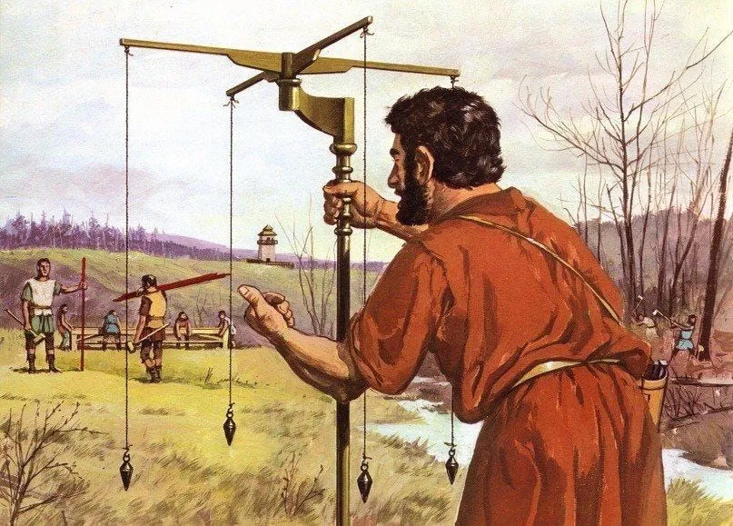
Operational Techniques
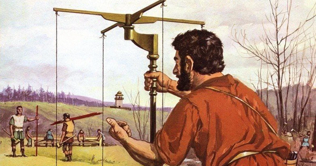
The surveyor positioned the groma by driving the ferramento into the soil or placing it atop a special stone called ad lapidem that traveling gromatici carried with them. A fifth plumb line hanging from the cross center allowed precise positioning of the umbilicus soli directly over the reference marker on the ground. The surveyor verified vertical alignment by checking that all plumb lines hung freely without touching the staff.
Once properly positioned, the gromaticus rotated the cross to align two opposite plumb lines with the desired direction. An assistant walked backward along that line while the surveyor sighted through the two strings, directing the assistant left or right until perfect alignment was achieved. The assistant then planted a marker pole at that distant point.
The surveyor could verify right-angle accuracy by walking around the instrument without disturbing it and checking whether the perpendicular plumb lines aligned with a previously established marker. This technique allowed three points to be aligned simultaneously: the previous reference marker, the current groma position, and the new forward marker. Repeating this process created perfectly straight lines extending for miles across varied terrain.
Measuring Distances
Surveyors measured distances between groma stations using standardized wooden rods. Teams of rod carriers walked the surveyed line, placing each rod end-to-end and counting the total number required to cover the distance. This method worked effectively on level ground or gentle slopes where terrain irregularities introduced minimal error.
Crossing steep valleys created measurement complications that surviving sources never fully explain. The groma could establish line direction but provided no altitude measurements. Surveyors apparently used separate leveling instruments or techniques to account for elevation changes when calculating true horizontal distances.
Accuracy tests conducted on surviving centuriation grids show that Roman surveyors achieved remarkable precision despite the groma’s limitations. The inherent angular error caused by optical illusion, where the far plumb line appears thinner than the near one, introduced approximately 1.5 millimeters of deviation per meter. Over the standard centuria plot measuring 710 meters per side, this accumulated to roughly one meter of error.
Built out of a love for history, kept free from distractions.
Spoken Past is an independent project shaped by curiosity, care, and long hours of research. Reader support helps keep it maintained, carefully researched, and open to everyone.
Wind Interference Problems
Wind posed the most serious operational challenge for groma users. Even moderate breezes caused the hanging plumb bobs to swing, making accurate sighting impossible. Surveyors working in exposed locations or during windy seasons could not use the instrument effectively.
The dioptra, a more sophisticated Greek surveying instrument, performed better in wind because it used mechanical sighting tubes rather than hanging strings. Romans knew about the dioptra but apparently preferred the simpler, cheaper groma for most surveying tasks. The groma’s extreme simplicity meant that any trained assistant could operate it, while the dioptra required specialized technical knowledge.
Contemporary sources provide no solutions for the wind problem beyond waiting for calmer conditions. The preference for groma despite this significant limitation suggests that Mediterranean weather patterns generally provided sufficient calm days for completing surveying projects on schedule.
The Chorobates Leveling Instrument
Vitruvius described the chorobates as more precise than contemporary water levels for measuring horizontal planes. The standard design featured a wooden beam twenty Roman feet long, approximately six meters, supported by legs or brackets at each end. Two plumb lines hung from the beam ends, aligning with vertical marks carved into the support structures.
When the beam sat perfectly level, both plumb lines matched their respective reference marks simultaneously. Diagonal braces connecting the legs to the beam featured carved notches that also aligned when proper leveling was achieved. This redundant verification system reduced the chance of measurement errors.
A shallow groove or channel carved along the top of the beam provided an alternative leveling method for windy conditions. The surveyor filled this channel with water and checked whether the liquid surface touched both ends of the groove equally. Water leveling eliminated the wind interference that rendered plumb bobs useless in breezy conditions.
Interpreting Vitruvius on Chorobates Design
Isaac Moreno Gallo, a technical engineer specializing in Roman civil engineering, challenged the standard chorobates reconstruction in 2004. He argued that modern table-shaped replicas misinterpret Vitruvius due to incorrect translation of the Latin term ancones. This word could mean legs but also means brackets or corbels, suggesting a vertical rather than horizontal support structure.
Sixteenth-century illustrations consistently depicted vertically-oriented chorobates designs. Jean Goujon’s 1547 French translation of Vitruvius showed vertical brackets supporting the beam. Miguel de Urrea’s 1582 Spanish edition and Juan de Lastanosa’s later publication of Gianello della Torre’s engineering works maintained this vertical interpretation.
Claude Perrault’s 1673 translation radically altered the representation, introducing the horizontal table-like design that became standard in modern reconstructions. Moreno Gallo argues that vertical brackets make more sense from a practical topography perspective and preserve the original twenty-foot length that table designs often reduce. His working replicas demonstrate that the vertical configuration functions more effectively for optical leveling than horizontal alternatives.
Applications in Road Construction
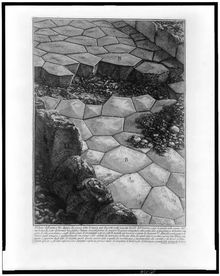
Roman road builders used beacons positioned on hilltops to establish initial route alignments across long distances. Surveyors then employed the groma to verify and refine these beacon placements, ensuring perfect linear accuracy. The process required positioning the instrument at each beacon location and sighting along the plumb lines to align the previous beacon, current position, and next beacon simultaneously.
In forested terrain where direct line-of-sight was impossible, surveyors lit fires at beacon positions and used the smoke columns as visual targets. This technique allowed alignment through dense vegetation that would otherwise block direct observation. The work proceeded slowly but produced the famously straight Roman roads that facilitated rapid military movement and commercial transport.
Moving between beacon stations and repeatedly checking alignments required days or weeks depending on route length and terrain difficulty. The resulting precision justified the time investment because straight roads minimized distance and construction effort compared to routes that followed existing terrain features.
Centuriation and Land Division
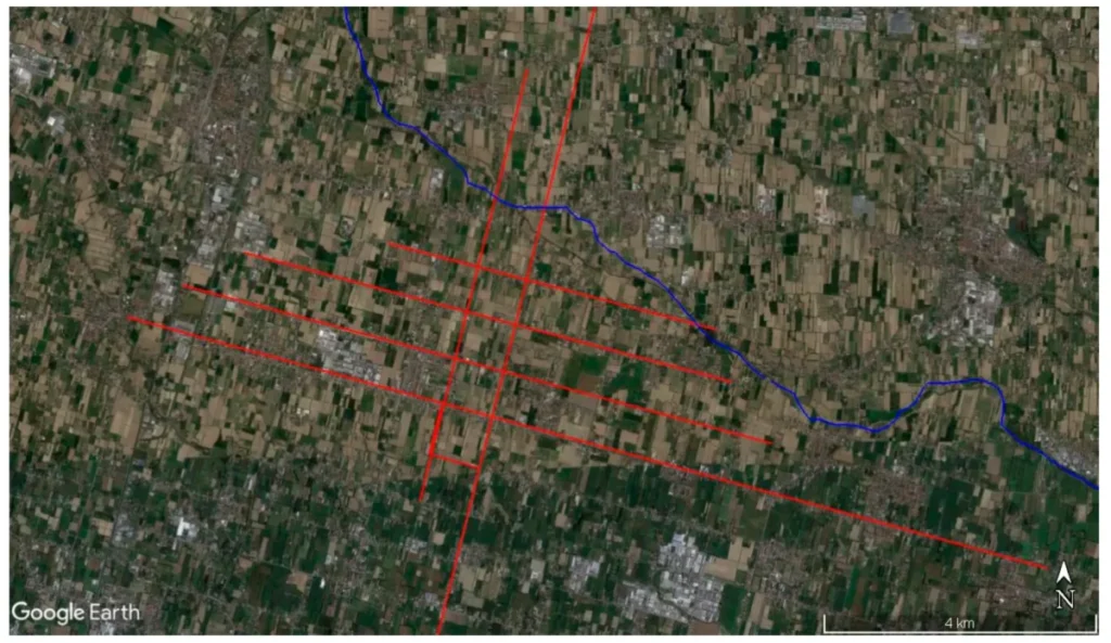
Roman centuriation projects divided agricultural land into square plots bounded by roads and drainage channels. The standard centuria measured 710 meters per side, containing 200 iugera of farmland. Surveyors used the groma to establish the primary axes called cardo and decumanus, then subdivided the grid into individual plots.
Veterans discharged from military service received centuriated land as retirement compensation beginning in the second century BCE. This systematic colonization program required surveying millions of acres across Italy, North Africa, and the provinces. The scale of Roman centuriation exceeded all previous Mediterranean land division programs by orders of magnitude.
Aerial photography reveals ancient centuriation patterns still visible in modern landscapes across southern Europe and North Africa. The geometric regularity of these surviving grids testifies to Roman surveying accuracy achieved using simple instruments like the groma.
Aqueduct Gradient Measurement
Aqueduct construction demanded precise gradient control to maintain water flow over distances exceeding 50 miles in some cases. The chorobates enabled Roman engineers to measure subtle elevation changes and maintain consistent downward slopes of approximately 0.5 percent. This shallow gradient prevented water from flowing too rapidly and eroding the channel while ensuring sufficient velocity to prevent sediment accumulation.
Engineers established reference points along the proposed aqueduct route using the chorobates to verify level planes. Cumulative measurements allowed calculating total elevation drop between the source and destination. The famous Pont du Gard aqueduct in southern France demonstrates the precision achievable with these ancient leveling techniques.